


Building an Online Banking System Architecture with AI-Powered C4 PlantUML Studio
Discover how AI-Powered C4 PlantUML Studio simplifies designing online banking system architecture with AI-generated diagrams and live editing.
Creating a comprehensive software architecture for a complex system like an online banking platform can be a daunting task, requiring deep technical knowledge and significant time. However, with the AI-Powered C4 PlantUML Studio from Visual Paradigm, you can streamline this process dramatically. This powerful, web-based tool guides you through a structured workflow, using AI to generate the initial diagrams based on your problem statement, which you can then refine in a live, split-screen editor. The result is a clear, professional, and easily shareable visual representation of your system’s design. This case study will walk you through the entire process, demonstrating how this tool can transform the way you design and document software architecture.
Key takeaways:
-
Use the AI-Powered C4 PlantUML Studio to quickly generate professional architecture diagrams.
-
Start with a clear problem statement to guide the AI in creating accurate diagrams.
-
Refine AI-generated diagrams in a live editor to perfect your design.
-
Visualize your system at multiple levels: context, containers, components, and deployment.
-
Share your architecture with stakeholders using a simple, read-only link.
Step 1: Define the Problem Statement
The first step in any architectural endeavor is to clearly define the problem you are solving. In the AI-Powered C4 PlantUML Studio, this begins with the “Problem Statement” tab. Here, you provide a detailed description of your system. For our case study, the project is an “Online Banking System.” The user has already input a project name and then clicked the “AI-Assist: Generate Full Problem Statement” button. This powerful feature uses AI to analyze the context and generate a comprehensive, structured problem statement for you. This statement serves as the foundation for all subsequent diagrams, ensuring they are contextually relevant and accurate. The generated text outlines the system’s purpose, its primary users (customers and bank staff), and its key interactions (account checks, transfers, payments), setting a solid foundation for the design.

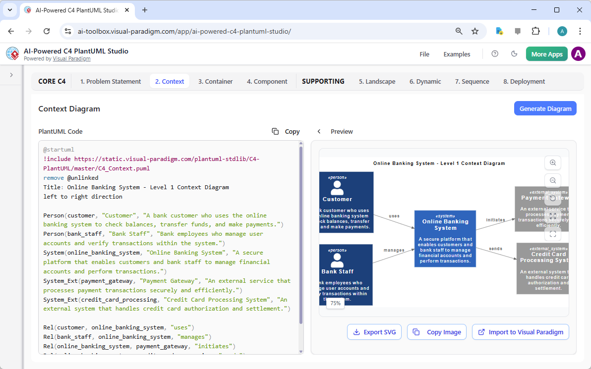
Step 2: Generate the Context Diagram
Once the problem statement is defined, you move to the “Context” tab. This is where the C4 model begins to take shape at the highest level. The AI, having processed the problem statement, can now generate a “System Context” diagram. This diagram shows your system as a single entity and its interactions with external users and systems. In the screenshot, the AI has generated a clear diagram with the “Online Banking System” at the center, connected to “Customer” and “Bank Staff” as primary users, and “Payment Gateway” and “Credit Card Processing System” as external systems. The diagram is generated from PlantUML code, which is visible in the editor on the left, and the visual preview on the right updates in real-time. This allows you to immediately see the visual impact of the AI’s work and make any necessary adjustments.
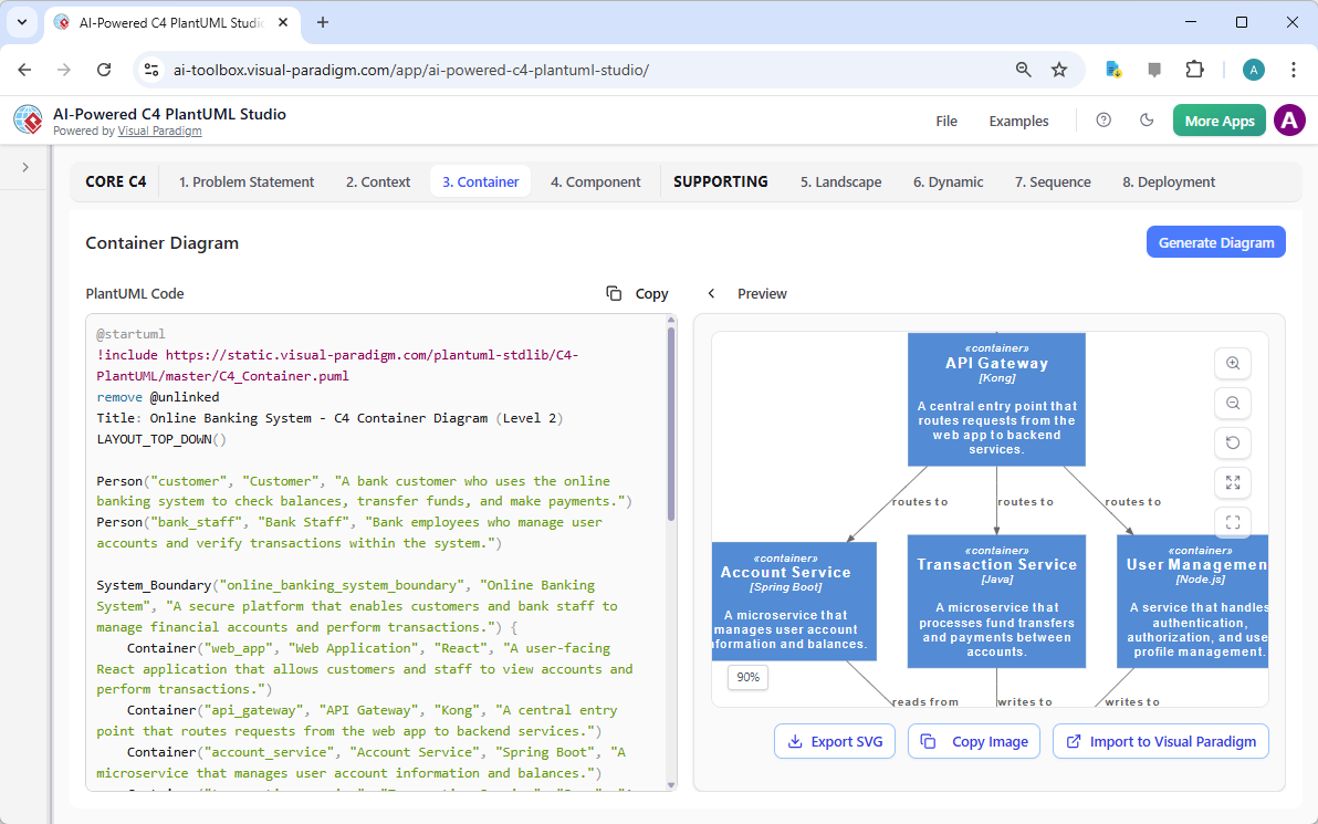
Step 3: Create the Container Diagram
Next, you dive deeper into the system’s structure by moving to the “Container” tab. This diagram breaks down the main system into its high-level technical components, such as web applications, APIs, and databases. The AI uses the information from the problem statement and the context diagram to generate a logical and relevant container diagram. In this example, the AI has identified key containers like the “API Gateway,” “Account Service,” “Transaction Service,” and “User Management.” The diagram clearly shows how these containers interact, with arrows indicating the flow of requests and data. The live preview ensures you can instantly see the results of any changes made to the underlying PlantUML code.
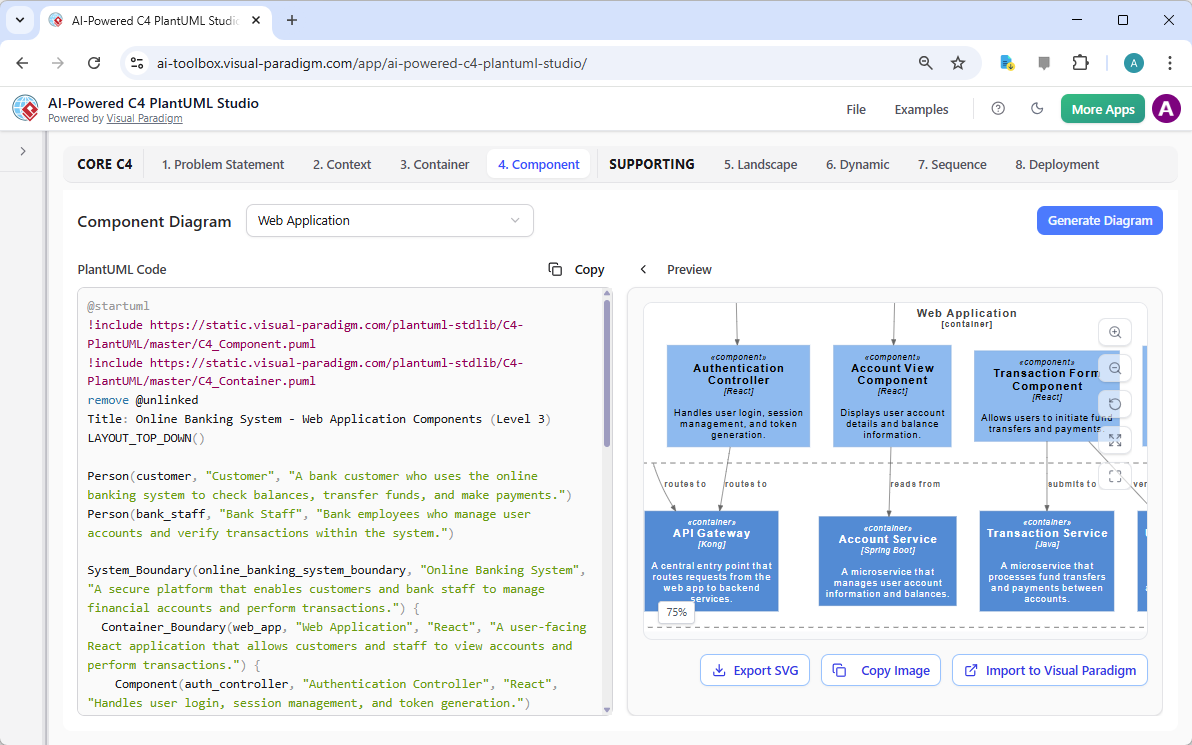
Step 4: Develop the Component Diagram
From the container level, you can now zoom in on a specific container to explore its internal structure. The “Component” tab allows you to generate a detailed view of the components within a container. In this case, the user has selected the “Web Application” container, and the AI has generated a component diagram showing the internal structure of the user-facing application. This diagram includes components like “Authentication Controller,” “Account View Component,” and “Transaction Form Component,” each with a brief description of its function. This level of detail is crucial for developers to understand the internal workings of a specific part of the system. The split-screen editor allows for seamless refinement of the component structure.
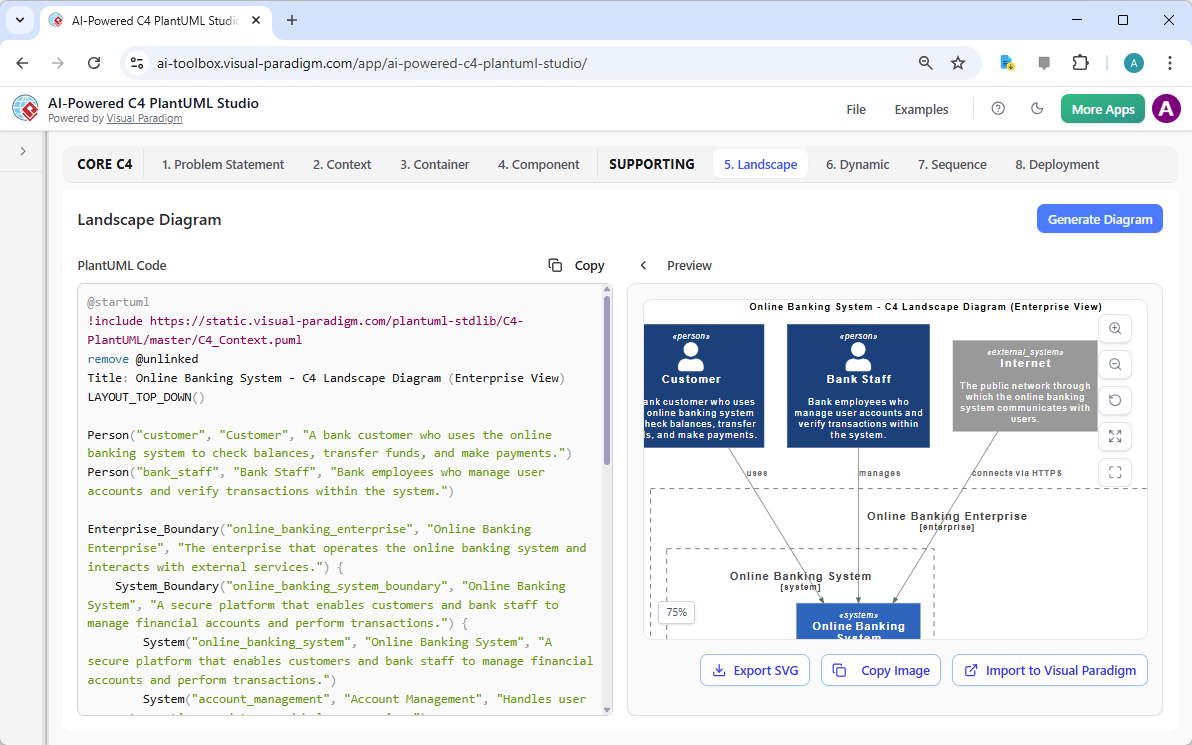
Step 5: Visualize the Landscape
While the core C4 diagrams focus on the system itself, the “Landscape” diagram provides a broader, enterprise-level view. This diagram shows the system in the context of the larger organization and its surrounding environment. The AI generates this diagram to illustrate how the “Online Banking System” fits within the “Online Banking Enterprise” and interacts with the public “Internet.” This view is particularly useful for stakeholders who need to understand the system’s place within the overall business ecosystem. The diagram clearly defines the enterprise boundary and shows the external connections, providing a comprehensive understanding of the system’s scope and dependencies.
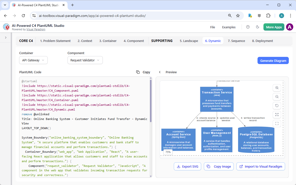
Step 6: Model Dynamic Behavior
To understand how the system operates, you need to model its dynamic behavior. The “Dynamic” tab allows you to create a “Dynamic Diagram” that shows the sequence of interactions between components. In this example, the user has selected the “Transaction Service” container and the “Request Validator” component. The AI has generated a diagram illustrating the flow of a “Customer Initiates Fund Transfer” process. The diagram shows the step-by-step interaction between the “Transaction Service,” “User Management,” and “PostgreSQL Database,” with clear labels for each message. This helps to identify potential bottlenecks, security issues, and the overall flow of the system’s operations.
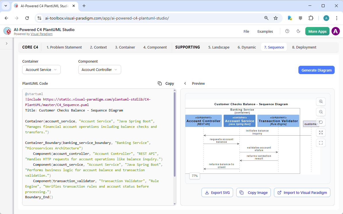
Step 7: Detail Sequence Interactions
For even more granular insight into system behavior, the “Sequence” diagram provides a detailed view of the interactions between components during a specific use case. In this case, the AI has generated a “Customer Checks Balance” sequence diagram. This diagram shows the precise sequence of messages between the “Account Controller,” “Account Service,” and “Transaction Validator.” The clear, chronological flow helps to understand the system’s logic and the dependencies between components. This level of detail is invaluable for debugging, performance analysis, and ensuring that the system behaves as expected under various conditions.
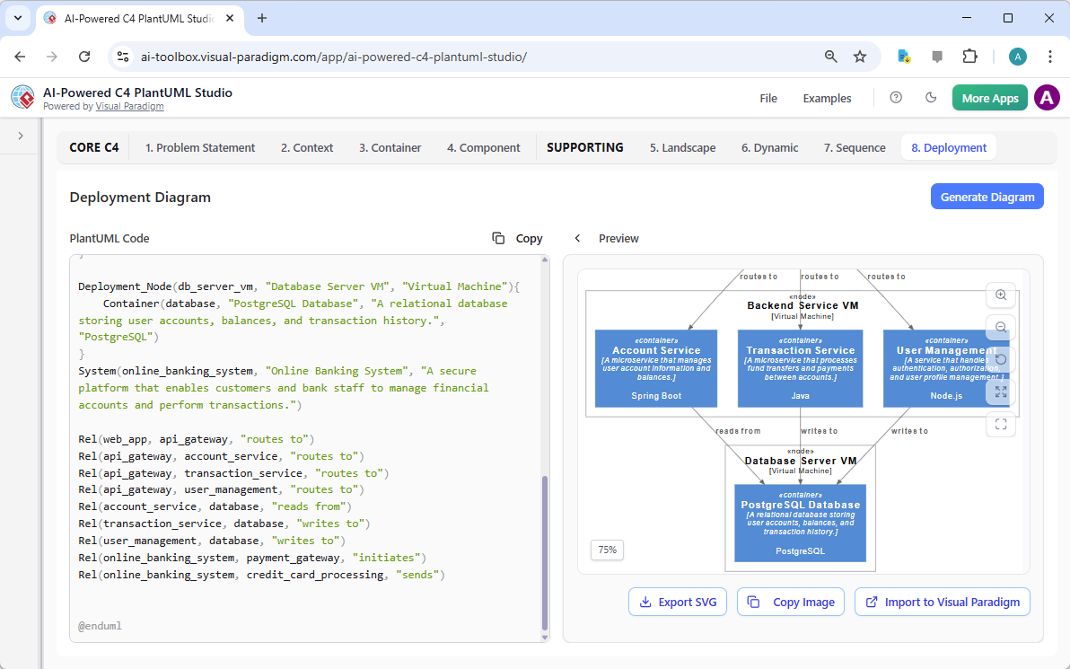
Step 8: Plan the Deployment
The final step in this architectural journey is to plan the system’s deployment. The “Deployment” tab allows you to create a “Deployment Diagram” that shows how the software components are mapped to the physical or virtual infrastructure. The AI has generated a diagram showing the “Backend Service VM” hosting the “Account Service” and “Transaction Service,” the “Database Server VM” hosting the “PostgreSQL Database,” and the “User Management” service running on a “Node.js” server. This diagram is essential for DevOps teams to understand the system’s infrastructure requirements and for ensuring that the system can be deployed and scaled effectively.
By following this structured, AI-assisted workflow, you can rapidly create a comprehensive and professional software architecture for your online banking system. The AI-Powered C4 PlantUML Studio from Visual Paradigm is a powerful tool that simplifies complex design processes, reduces errors, and improves communication across teams. It’s an essential resource for software architects, developers, and students who need to design and document complex systems efficiently.
Ready to build your own software architecture? Try the AI-Powered C4 PlantUML Studio today and experience the power of AI-assisted design. Try Now.
Related Links
The C4 model is a hierarchical software architecture technique used to visualize systems at four distinct levels of abstraction: Context, Containers, Components, and Code. Visual Paradigm offers specialized tools to create these models, including AI-driven automation through the C4-PlantUML Studio, which can transform natural language descriptions into layered architecture diagrams. These features are designed to streamline the documentation lifecycle, ensuring that complex system designs remain scalable, maintainable, and clear for both developers and stakeholders. Recent updates have introduced full C4 model support across desktop and cloud platforms, enabling teams to use AI chatbots to instantly generate and refine component diagrams for various system types.
-
Beginner’s Guide to C4 Model Diagrams: A foundational step-by-step introduction to creating diagrams across all four C4 levels for effective communication.
-
C4 Model Tool – Visualize Software Architecture with Ease: An overview of the dedicated toolset used to manage architectural models at multiple levels of abstraction.
-
AI-Powered C4-PlantUML Studio Diagram Generator: Details on a tool that combines AI automation with PlantUML flexibility to build C4 diagrams from text.
-
Leveraging AI C4 Studio for Streamlined Architecture Documentation: A guide focused on using AI to maintain clean and scalable documentation for modern software systems.
-
C4 Model Templates – Ready-to-Use Designs: A library of professionally designed templates to help teams quickly visualize system designs during planning.
-
Unveiling the Power of C4 Model: Simplifying Architecture Diagrams: An article exploring how cloud-based platforms simplify the creation of accurate C4 models.
-
Visual Paradigm Full C4 Model Support Release Notes: Documentation on the latest features enabling comprehensive C4 diagram management in Visual Paradigm.
-
A Comprehensive Guide to AI-Powered C4 PlantUML Studio: An exploration of how generative AI creates layered, reliable diagrams from natural language input.
-
C4 Model AI Generator: Automating Lifecycle Management: A look at how AI chatbots automate the modeling lifecycle to provide consistent results for DevOps and cloud teams.
-
The Ultimate Guide to C4-PlantUML Studio Design: A resource detailing how AI-driven automation enhances the clarity and flexibility of software architecture design.